5.2.4 Runway
Runways can also be placed freely on the landscape, but they need to be assigned to an airport. Runways support flying ILS approaches.
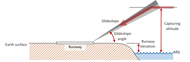
The vertical geometry of an ILS approach is defined by the following parameters (in red):
A runway has the following properties:
|
|
Element |
Purpose |
|
1 |
LOCATION |
The location is mandatory and defines the geographic coordinates of the center of the runway. It consists of longitude and latitude. |
|
2 |
ALTITUDE |
Altitude of the runway in meter above sea level. |
|
3 |
LENGTH |
Length of the runway in meters. |
|
4 |
DIRECTION |
Direction (primary) between 0° and 360°. The reverse direction does not exist as an attribute but is derived from this property. |
|
5 |
PRIMARY RUNWAY ID |
The ID of a runway is formed by the first two digits of the direction
(e.g. direction = 73° -> ID = 07, Parallel runways are suffixed with L, R or C: |
|
6 |
PRIMARY FREQUENCY |
The next three properties are optional and describe the ILS approach to the primary runway direction. If the navigation receiver on the groundstation is tuned to this frequency, deviations from the ILS glideslope will be indicated on the Primary Flight Display and on the Navigation Display. Like the frequency of any navigation aid, each ILS frequency needs to be distinct within the whole navigation database. |
|
7 |
PRIMARY GLIDESLOPE ANGLE |
The primary glideslope angle is the vertical angle between the glideslope and the horizontal earth surface. While real ILS typically have 3° glideslope angles, for multicopters 20° is recommended and for fixed wing planes maybe 10°. This property is only required if a frequency has been specified. |
|
8 |
PRIMARY INTERCEPTION ALTITUDE |
The interception altitude in meters is the altitude at which the final approach ideally begins. In reality this altitude is 2000´ to 3000´ above the runway. For FlightZoomer the interception altitude typically would be defined 50m to 70m above the runway. |
|
9 |
REVERSE RUNWAY ID |
The ID of the reverse runway is formed by the first two digits of the
opposite direction (e.g. direction = 73° -> opposite direction =
253° -> ID = 25, Parallel runways are differentiated as described under PRIMARY RUNWAY ID. |
|
10 |
REVERSE FREQUENCY |
The next three properties are also optional and describe the ILS approach to the reverse runway direction. If the navigation receiver on the groundstation is tuned to this frequency, deviations from the ILS glideslope will be indicated on the Primary Flight Display and on the Navigation Display. The frequency of the reverse runway ILS must not only be different than the frequency for the primary direction but also distinct from any other ILS or navigation aid frequency. |
|
11 |
REVERSE GLIDESLOPE ANGLE |
The reverse glideslope angle is the vertical angle between the reverse glideslope and the earth surface. For details see PRIMARY GLIDESLOPE ANGLE. |
|
12 |
REVERSE INTERCEPTION ALTITUDE |
The interception altitude in meter is the altitude, at which the final approach ideally begins. For details see PRIMARY INTERCEPTION ALTITUDE. |